Analyses
The requirements for the RC baja drivetrain are listed below:
1.The car must be conceived, designed, and fabricated by students without any direct involvement from professional engineers, automotive engineers, or related professionals.
2.One propulsion motor per vehicle: Any motor which conforms to current-vintage ROAR brushed or brushless specifications and manufacture is legal.
3.Baja TIME-LIMIT, equivalent to running the full course at 1.0 MPH.
4. Lipo 2S 7.4 volt battery-pack intended for RC use.
5. Drivetrain must fit within maximum dimensions of 300x220x300mm.
6. Be able to reach and sustain top speed of 40 mph.
7. Be able to drive for at least 10 minutes and maintain full RPM.
8. Motor must be able to transmit 9.507 lb-in of torque.
9. Upon impact the center spool mount cannot deflect by more than 0.1 mm.
10. 12-tooth pinion gear center distance be less than 1inch.
11. 3D printed Mounts with PETG plastic.
12. Be able to accelerate at 7ft/s/s.
13. Be able to decelerate at -5ft/s/s.
Analysis 1 shows the calculation for finding the desired top speed. Step one is to find the motor KV to then be able to determine the top speed of the RC vehicle. The motor type chosen gives that 13.5T = 3,300 RPM. From that given information and using a voltage of 7.4V for the battery the motor KV can be calculated using the equation: KV = RPM/V, as shown in the analysis. The next step will be to use the chosen diameter size (D=3.4 inches) for the tires in order to calculate for the top speed (shooting for 25mph).
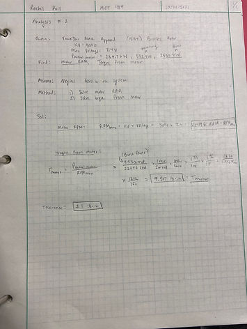
Analysis A-1: Actual Power of Motor
In analysis 1, the actual power of the motor for the RC car is to be determined using the given values for KV (3040KV) and current (operating current=80A, burst current=380A) provided in the description of the 69T TrackStar ROAR approved brushless motor. Using the battery voltage of 7.4V and the current of the motor, the calculated values for the operating power and the burst power were found from the equation P=IV, where P is power, I is current and V is volts. From there the actual power equation was used to determine actual power outputs of 532.8W for the operating current and 2530.8W for the burst current. The tolerance is +/- 5W.
Requirement: Reach top speed of 40 MPH, given a tire diameter of 3.4 inches.
Analysis: Finding the gear ratio
Design: 5.75 gear ratio using a 69tooth spur gear with a 12 tooth pinion. Top speed calculated was 39.6 MPH.
Analysis A-2: Motor RPM, Torque of Motor
In analysis 2, the motor RPM was found using the equation RPM(max)= KV x Voltage = 3040 KV x 7.4V = 22496 RPM. Next, the torque of the motor was calculated to be 9.507 lb-in with a tolerance of +/- 1 lb-in. This was found using the equation Torque of motor = Actual Power of Motor / RPM max.
Analysis A-3: RPM Wheels, Max Speed
In the third analysis, the RPM of the wheels are determined to then find the maximum speed the RC vehicle can get to. The first step was to determine the gear ratio, which was found using 69 Tooth spur gear / 12 tooth pinion to get a gear ratio of 5.75. Then the RPM to the driveshaft can be calculated using the equation RPM to driveshaft = Max RPM of Motor / Gear Ratio, which gives a value of 3912.35 RPM. From here, the RPM of the wheels was calculated to be 3912.35, as well because there is no differential being used for the RC car. The tolerance is +/-10 RPM.
The second part of this analysis is to determine the max speed given the outer diameter of the wheels are 3.4 inches. Calculations to find the that 1 revolution of the tires gave a value of 1.6856 x 10^(-4) miles. Final step is to multiply the by the RPM of the wheels and convert to MPH: 3912.35RPM x 1.6856 x 10^(-4)miles x (60min/1hr) = 39.6 MPH for the max speed. The tolerance is +/- 1 MPH.
Analysis A-4: Acceleration and Deceleration of Vehicle
The purpose for analysis 4 is to determine the acceleration as well as the deceleration of the RC vehicle. The requirement for this analysis is that the car must be able to accelerate in 7 ft/s/s and decelerate in 5ft/s/s. To compute theses values the average velocity of the car was divided by the time it takes the car to reach full speed (or reach 0mph from full speed for deceleration value). Using the top speed computed for the car of 40MPH and the time to reach this value of 8.37 seconds, the average acceleration of the car was calculated to be 7ft/s/s, which supports the requirement of this car to be able to accelerate at 7ft/s/s. To calculate the deceleration of the car the top speed velocity of 40MPH was divided by the time it takes the car to reach 0 MPH from the top speed (11.72 seconds), which was -5ft/s/s, thus supporting the design requirement of the car to be able to decelerate at -5ft/s/s.
Analysis A-5: Torque on Axle
The torque on the axle was calculated to be 54.7 lb-in, as shown in appendix A-5 (Torque on Axle). The design requirement suggested by the manufacture was to use a gear ratio of 5 to 1 or higher, so a gear ratio of 5.75 was used. The torque of the motor is to be 9.507 lb-in. Using these requirements, the calculated parameter was 54.67 lb-in for the torsional stress on the axle. This is documented in #RMK-55-012. Factor of safety is 4.
Analysis A-6: Torsional Max Shear on Axle
Torsional max shear stress of the axle was determined to be 213000 psi, as shown in appendix A-6 (Max Shear Stress of Axle). After comparing this value to the yield stress of a low carbon steel material (sourced from www.matweb.com), which has a yield strength of 220000 psi, it was concluded that this could be a potential material match for the steel used in the axle purchased for the RC vehicle. The design requirement was to use 1.75mm for the radius of the axle and 54.67 lb-in for the torque on the axle. The calculated analysis was found to be 213000 psi for the torsional maximum shear stress on the axle.
Analysis A-7: Static Forces on Center Spool Mount
One engineering method used in analysis A-7 was the use of statics in order to find all the forces acting on the center spool mount. The purpose of this analysis was to ensure that the max stress on the mount would not exceed the yield stress of the PETG plastic being used to model the mount, which is 4,000 psi. To calculate the max stress, a static force analysis was performed on the mount and forces were found using the sum of forces in the vertical direction at equilibrium. After drawing a FBD and locating where the forces are acting, using equilibrium--The tangential force was calculated to be 77.17 lb (acting purely vertical), and the two forces acting on the top of the mount were found to both be 38.6 lbs. Next, the maximum stress was found to be 1,017 psi, which is less than the yield stress of 4,000 psi.
Analysis A-8: Stress on Center Spool Mount
Stress analysis of the center spool mount design. Reference appendix A-8 (Max Stress on Center Spool Mount) for this analysis. The requirement for this analysis is that upon impact the max stress must not exceed the yield stress of the PETG plastic, which is 4,000psi. In order to achieve this, the forces acting on the mount (radial and tangential) were calculated (shown previously in analysis 7). Then, the maximum stress of 876 psi was found to be far less than the yield stress of the material (4,000psi), which supports the design parameter of a thickness of .02in for the mount design.
Analysis A-9 : Force and Stress Analysis on Motor Mount
Engineering method used : Dynamics.
Force and stress analysis of the motor mount design. Reference appendix A-9 (Forces and Max Stress on Motor Mount) for this analysis. The requirement for this analysis is that upon impact the max stress must not exceed the yield stress of the PETG plastic, which is 4,000 psi. In order to achieve this, dynamics was used to calculate the forces acting on the mount. The force on the gear is 77.15lb, the force on the bearing is 38.57 lb., and the tangential force is 19.56 lb. Assuming that the motor shaft hole mount does not carry load, all the loads will be distributed between the 6 pinion mounting holes, which was calculated to be 3.26lbs. Then, the maximum stress was found (887 psi) to be less than the yield stress of the material, which supports the design parameter of a thickness of .024 inches for the motor mount design. This allows a safety factor of 3, which will give negligible deformation.
Analysis A-10 : Bending Stress on Pinion Gear
Bending stress on pinion gear. Reference appendix A-10 (Bending Stress on Pinion) for this analysis. The requirement is that the center distance be less than 1inch. The excel sheet (screenshot can be found in appendix A-10) was used to find the values of the bending stress on the pinion and the center distance. The bending stress on the pinion was calculated to be 39,000 psi (far less than the yield stress of steel). The center distance was calculated to be 0.844 inches, which is less than 1 inch, so it meets the given requirement. This supports the design parameter of using a 12-tooth pinion gear.
Analysis A-11 : Contact Stress on Pinion Gear
Contact stress on the pinion gear teeth. Reference appendix A-11 (Contact Stress on Pinion) for this analysis. The requirement is that the center distance be less than 1inch. The excel sheet (screenshot can be found in appendix A-11) was used to find the values of the contact stress on the pinion and the center distance. The contact stress on the pinion was calculated to be 140,000 psi. The center distance was calculated to be 0.844 inches, which is less than 1 inch, so it meets the requirement. This supports the design parameter of using a 12-tooth pinion gear.
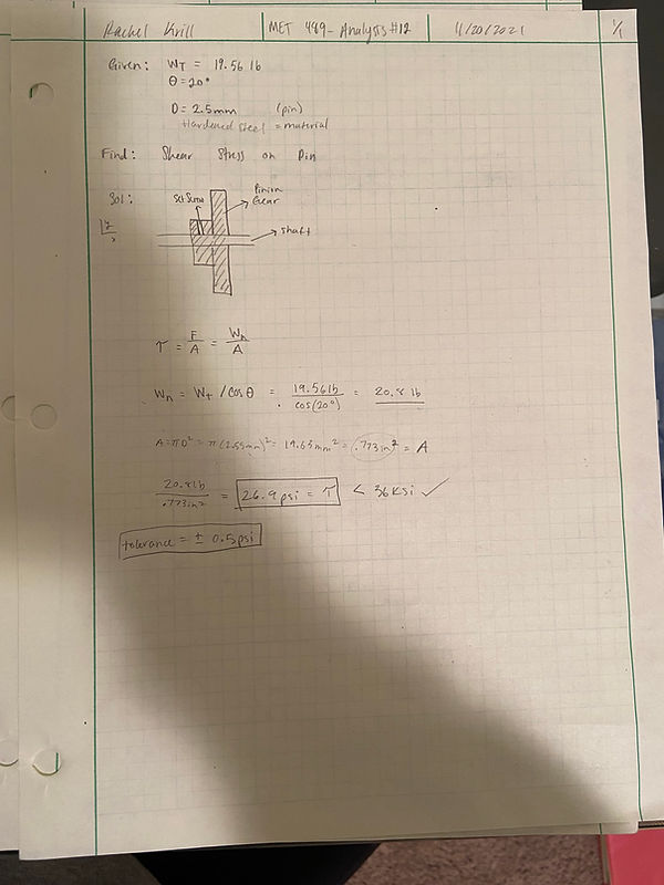
Analysis A-12 : Shear Stress on Set Screw
Shear stress on set screw. Reference appendix A-12 for the calculations of this analysis. The requirement was that the shear stress must not exceed the yield strength of steel. To find the shear stress on the screw, the area of the screw is divided by the force acting normal to the pin. The shear stress was calculated to
be 26.9 psi, which is substantially less than the yield stress of the material (steel) being 36 ksi. This supports the design parameter of a screw diameter of 2.5mm.


.jpeg)


